Vision and Motion Control Lab
Micro-Controller learning process
- 8051 calculator: Build a calculator which can execute arithmetic calculation using 8051, 7-seg display and 4x4-keyboard. A 4x4 matrix keyboard which is polling by 8051 periodically to get integers that user inputted, the display using 74LS47 BCD decoder IC and 7-seg LED, an additional PNP transistor current amplifier is connected to drive 7-seg LED instead of direct driving by 8051. To save hardware resources, 7-seg LED output data bus was connected together, and be controlled with an enable signal from 8051.
- 8051 Alarm Clock: Base on calculator's hardware, modified its algorithm and circuit to make it equipped with alarm clock function. Using a flag variable to control system’s operating mode, and there’s two internal timer was set up, a transistor derived beeper used as alarm. The alarm function can be operate normally even in calculator mode, by setting a higher interrupt priority.
|
Experiment 1 (familiar software development environment keil uVision3)
|
| ||
|
Experiment 2 (familiar firmware development environment Keil uVision plus 8051 board)
|
| ||
|
Experiment 3 (logic circuit)
|
| ||
|
Experiment 4 (Port I / O)
|
| ||
|
Experiment 5 (7-segment display)
|
| ||
|
Experiment 6 (scanning technology --POLLING)
|
| ||
|
Experiment 7 (Electronic calculer)
|
| ||
|
Experiments 8 (interrupt use -INTERRUPT)
|
| ||
|
Experimental 9 (clock)
|
| ||
|
Experiment 10 (RS-232 serial communication port used)
|
| ||
Electromechanical Interfacing learning process
- Stepper motor control: To drive a stepper motor to rotate in a desired direction at a desired speed. Darlington transistors are switched in a proper sequence to connect power supplies to the two sets of armature field windings for the motor to rotate, the four bit sequence control string is loaded to a 74LS194 shift register by 8051 through a parallel port of 8255, the shift direction control mode of 74LS194 upon clock trigger is set through the other 8255 port by 8051, while the trigger to determine the motor speed is generated by 8254 whose time up value is altered by 8051 to change the period of trigger, namely, the stepping time and inversely the speed of the motor.
- Digital voice recorder & player: Record voice from Capacitor Microphone, store sampled digital signal in the flash memory and could be replay by speaker anytime. The voice signal sensor using a Capacitor Microphone and amplified by a AD620 instrumentation amplifier, the analog signal will pass an anti-aliasing LPF stage, then input to S&H IC LF398 which worked with another 74LS123 to sync the A/D conversion data holding time, ADC0804 is chosen as our ADC because of its price, it operate in 4k samples per second and 8bit resolution, the sampled data stored in AT89C51ED2’s internal extra 64K flash. The replayed bit-stream conversion back to analog signal by DAC800, and go through two 2nd order Sallen-key LPF as smooth filter, a LM384 audio amplifier IC is attached as the last stage to supply sufficient driving current to speaker.
|
Experiment 1 (divider and counter)
|
| ||
|
Experiment 2 (digital I / O control switch Experiment)
|
| ||
|
Experiment 3 (stepper motor Experiment)
|
| ||
|
Experiment 4 (A / D, D / A card use)
|
| ||
|
Experiment 5 (op-amp Experiment - Performance Test)
|
| ||
|
Experiment 6 (operating income conversion and signal amplifier Experiment ~ analog converter)
|
| ||
|
Experiment 7 (operational amplifier Experiment ~ noise prevention)
|
| ||
|
Experiment 8 (DA conversion experiments ~ DA converter application IC)
|
| ||
|
Experiment 9 (AD conversion experiments ~ AD conversion application IC)
|
| ||
|
Experiment 10 (digital audio recording Experiment & Complete MP3 circuit)
|
| ||
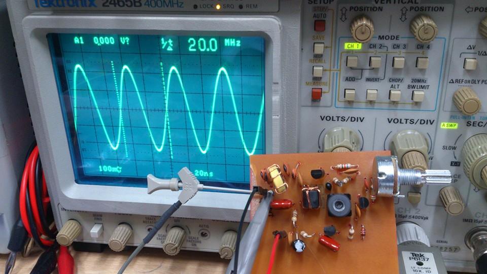
Voltage Control Oscillator
|
|
